NOVODICOM AI
for 3D MODELING INDIVIDUAL IMPLANTS
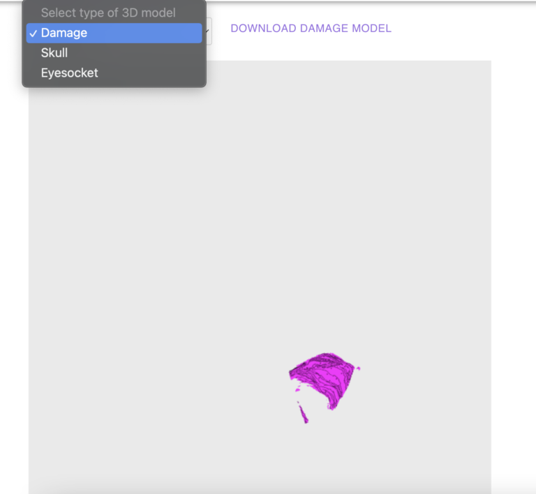
When modeling damage to thin small bones and bones of a complex shape of the facial skull, the following operations are performed: building a 3D model of bone damage, building a scan of the damage model, drawing a picture of the future implant, laser cutting the implant, cleaning and disinfecting the implant, finishing the implant to the desired geometry. Our application developed for assessing the condition of patients with damage to the bones of the orbit and automatically developed a three-dimensional model of the damage.
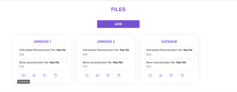
To get the result of the process, you must perform the following steps:

IN DETAIL
To get the result of the process, you must perform the following steps:
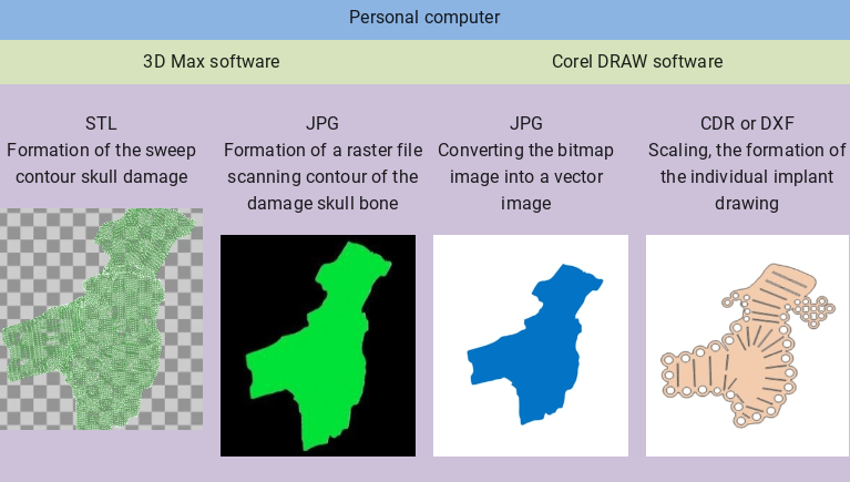
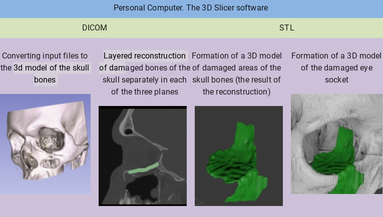
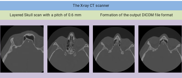
Figure 1 - Manufacturing technology of an individual implant for the replacement of the bones of the orbit
The following challenges arise.
Thin bones when generating a 3D model from the output files of an X-ray computed tomography disappear or look loose and full of holes.
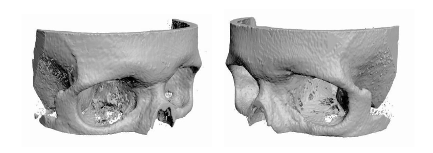
Figure 2 - 3D model of the orbit, built from the output files of X-ray computed tomography
Such results of 3D model generation make it difficult to accurately determine the location and size of bone lesions. Sometimes it is not at all clear from the model which of the bones is damaged and which is not.
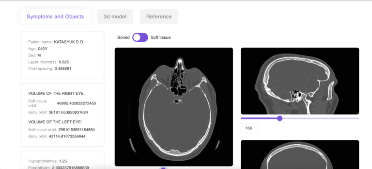
At present, we have developed and are operating an application that processes the output files of an X-ray computed tomograph (DICOM) and a web interface for it. The application automatically performs the following functions.
Function 1. When building a 3D model of the facial skull, all healthy thin and small bones will be clearly visible.
On the 3D model, it will be clear which bones of the orbit are healthy and which bones are damaged (Figure 3):
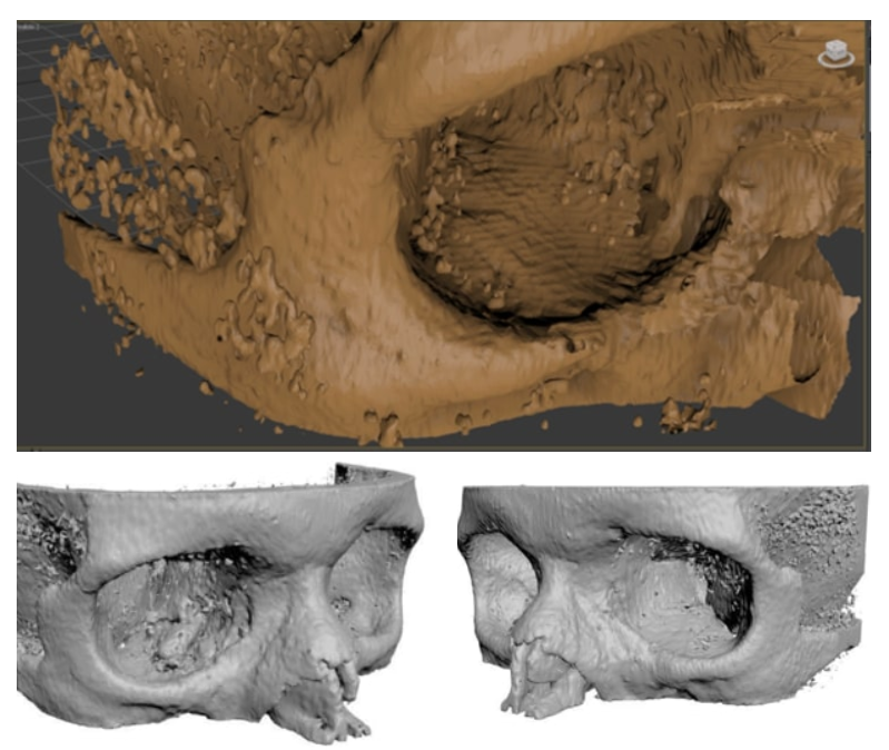
Figure 3 - 3D model of the orbit, built from the output files of the X-ray computed tomography processed by the application (equal to the model from Figure 2)
It can be seen that all the holes in the bones that were translucent on the original model (Figure 2) look like a solid bone on the resulting model.
Function 2. When constructing a 3D model of the facial skull, a 3D model of damage to the bones of the orbit (the geometry of broken bones) is built. When processing a damaged eye socket, the application automatically completes the bone in the place where it should be and removes the bone that remains. Therefore, when building a 3D model, a model of damage remains, and not healthy bones.
Figure 4 combines damage models built manually (green) and processed by the application (blue):
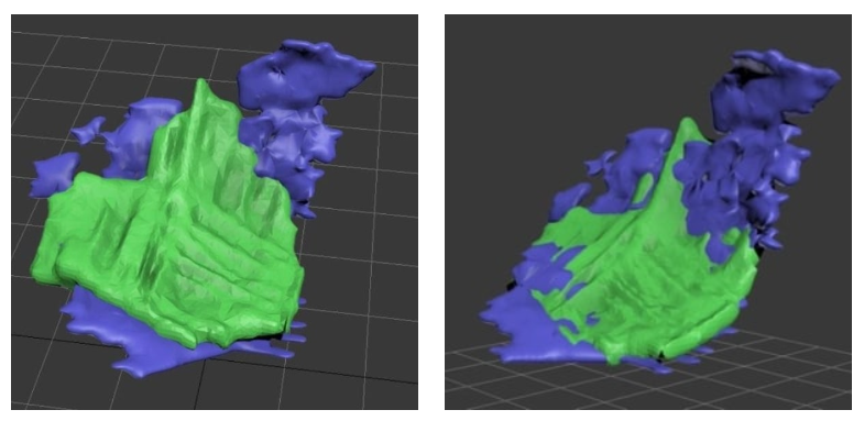
Figure 4 - 3D models of damage built in different ways
The results of building the damage model indicate that the processing of the original DICOM files in the application allows obtaining the geometry of bone damage in three-dimensional space. A detailed analysis of the layer-by-layer results of head scanning (DICOM files) shows that the algorithms used make it possible to obtain more accurate models of bone damage. The blue damage model is larger than the green one
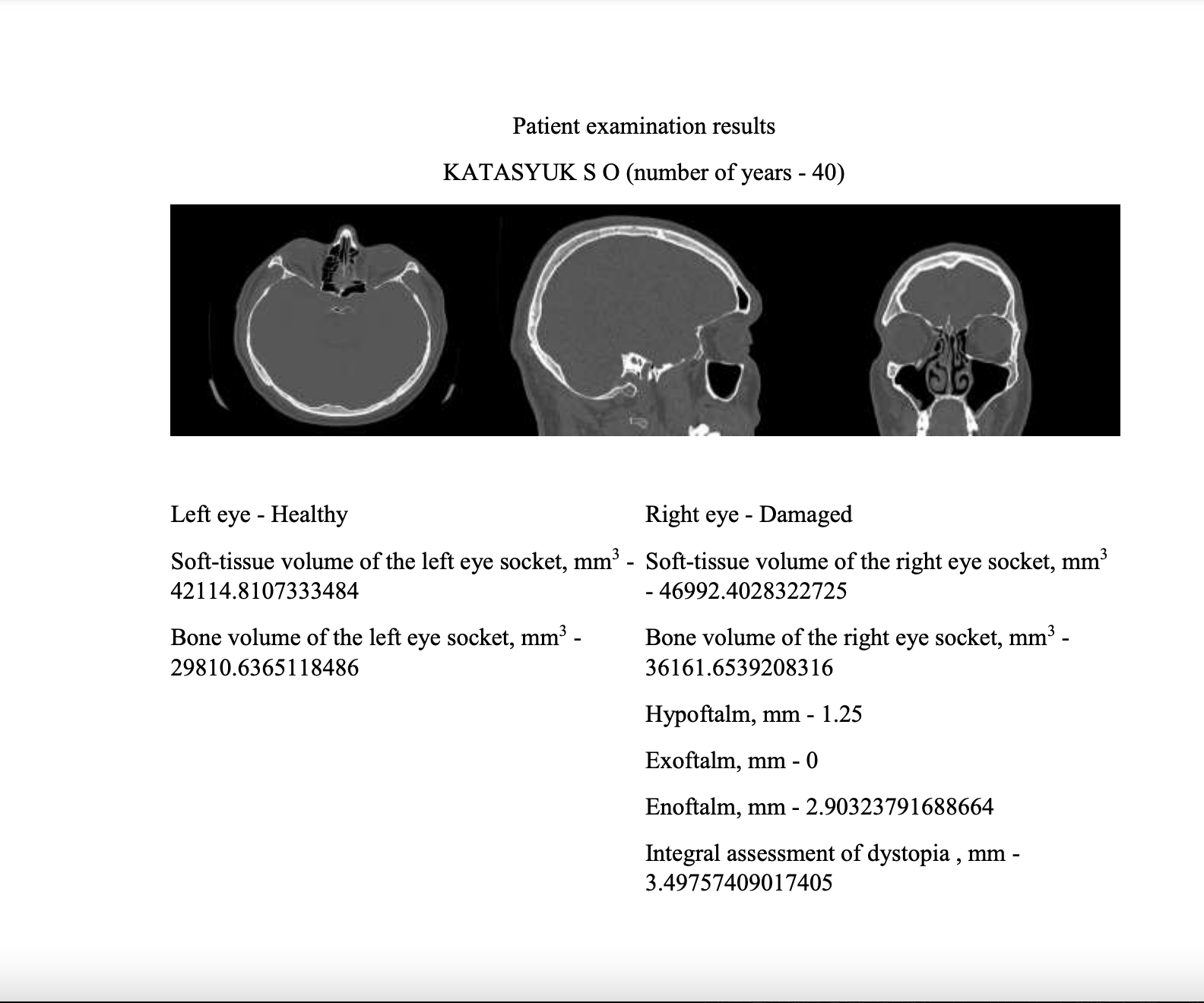
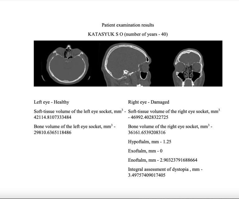
Function 3 Output to print and to a pdf-file of the results of calculating the parameters of a healthy and damaged eye sockets: dystopia, volumes of the bone and soft tissue orbits (Figure 5).
